In this article
The below procedure will update the IC on your GPD WIN 4 to resolve the refresh rate bug that has been found in the past few weeks. This GPD Win 4 60Hz fix does involve opening your GPD WIN 4 which can be a little tricky to do so. You will also need to buy a programmer and need another PC to perform the IC update. If you are unsure, do not attempt to open or perform the fix.
What parts you will need
Before starting, there is one absolute rule to follow: NEVER ATTEMPT TO SOLDER TO THE TEST PADS.
This is unnecessary in every case and has an extremely high risk of ripping off a pad and making it impossible to fix or recover your GPD Win 4 in the future. It’s happened multiple times now to people who didn’t listen. Don’t join the list!
If you follow this rule, it is essentially impossible to permanently brick your screen.
Standard parts
(You may have these on hand or have things that can be substituted)
- Dupont cables: standard 2.54mm spacing, I recommend the ribbon style ones so they stay straight – https://www.amazon.com/ELEGOO-Breadbord-Jumper-Wires/dp/B01EV70C78
- Pin header blocks: https://www.amazon.com/MCIGICM-Header-2-45mm-Arduino-Connector/dp/B07PKKY8BX
- 0.48mm pogo pins: do a search for “P50-B1”
https://www.amazon.com/Yosoo-Spring-Pressure-P50-B1-0-68mm/dp/B019FGHZBG
Alternatively you can buy a pre-made 3P, single row, 2.54mm programming cable on AliExpress: https://www.aliexpress.us/item/3256802885515922.html
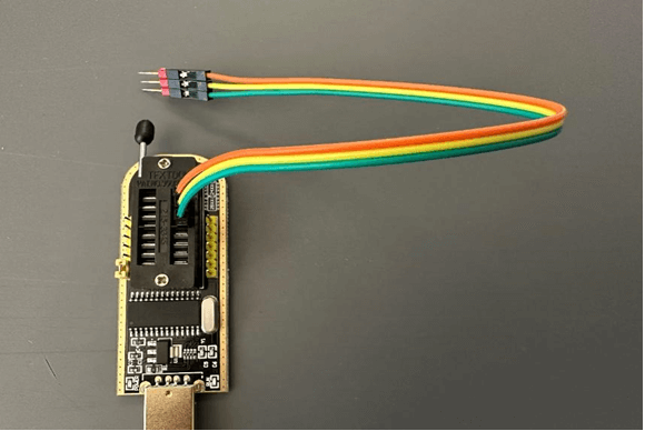
Programmer
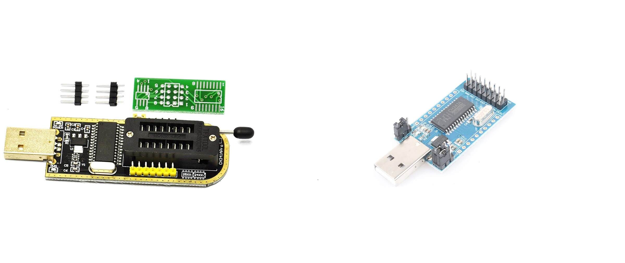
There are many different variations of the CH341a programmer. The easiest way to identify them is by PCB color, although there are several different versions of the black PCB CH341a that I know of.
Black, Green, and Blue PCB versions should all work, however you may need to adjust the wiring connections to match the programmer you’re using. (Green PCB programmers seem like they’re difficult to find now). Any CH341a based programmer should work as long as it has I2c connections
Example black CH341a: https://www.amazon.com/HiLetgo-Programmer-CH341A-Burner-EEPROM/dp/B014VSGH4Y
Example blue CH341a: https://www.amazon.com/NOYITO-CH341A-Serial-Parallel-Converter/dp/B082KQ75QM
Driver Download
Although the screen fix ZIP contains drivers for the CH341a, they do not work correctly. The correct drivers are the CH341PAR driver from the link below (thanks pelrun!)
CH341PAR – https://www.wch.cn/downloads/CH341PAR_EXE.html
If things do not work even after installing this driver, check the jumper on your programmer board. It must be on pins 1-2 for the black programmer, and on the I2C position for the blue one.
Programmer Assembly
Tear off 3 strands of dupont cables. We will want to end up with male on one side and female on the other side. If you only have female to female, you can break off a set of 3 pin headers to make it a male end
Break off a block of 3 pin headers. Remove the metal pins from the plastic block. Try not to crush the plastic.
Push the 0.48mm pogo pins through the 3 block of plastic. This should be a snug fit, be careful not to bend or crush the pogo pins as it may damage their spring actuation.
Once all 3 pogo pins are in place, push them into the female end of the dupont cables
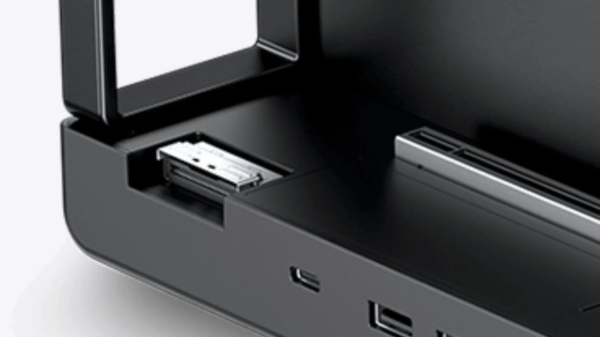
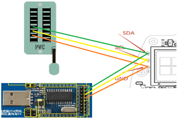
Latch down the other (male) end of the cable in the CH341a into pins 13, 14, and 15 (see images below). I have not used a blue CH341a programmer, however I included what should be the correct connections below
GPD WIN 4 Disassembly
Our GPD WIN 4 partial teardown can be used as a guide to open the GPD WIN 4. You only need to watch up to 4:56. Do not disconnect the battery as you will need to power on the device to flash it.
Programming
Download the IC software package: This mega link contains the software plus the correct drivers and has been re-packaged (thanks _ Λ𝓌メ _ !) to prevent confusion while flashing
https://mega.nz/folder/f1slhTAZ#qQvF8eZFWuFIhtSG3r7TMg
Alternatively, the original download link provided by GPD is:
https://drive.google.com/file/d/1dydUaVxUCgKxoSK6Jx4DDm3QH8BDOkEL/view?usp=share_link
Verify CH341 connectivity
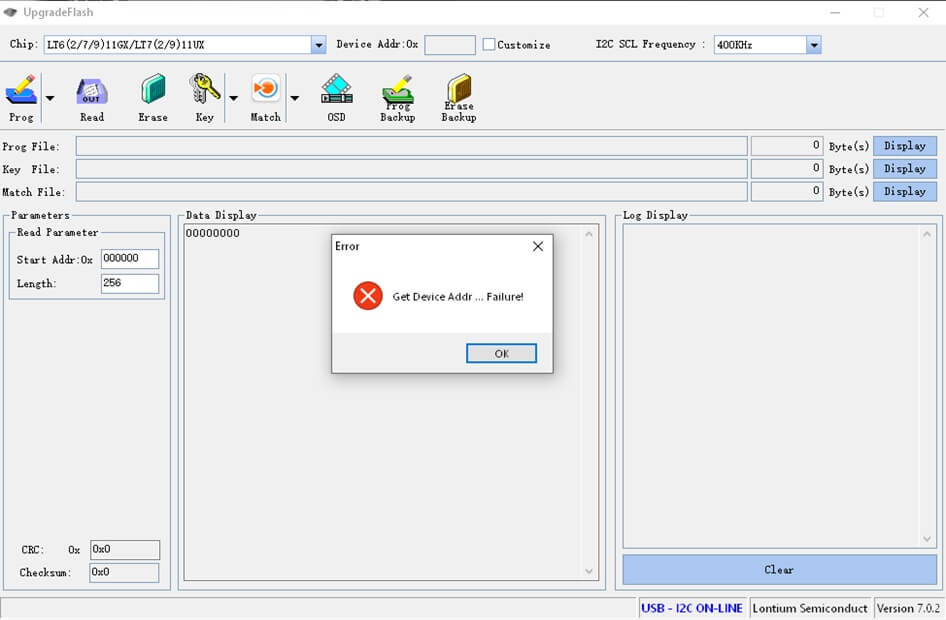
Open the “Upgrade_V7.0.2.exe” application.
If you open the application with the CH341a plugged in, you should see a blue “USB – I2C ON-LINE” on the bottom right corner, as well as an error message Get Device Addr … Failure! – this is normal. If the bottom right does not say USB-I2C ON-LINE, check your drivers
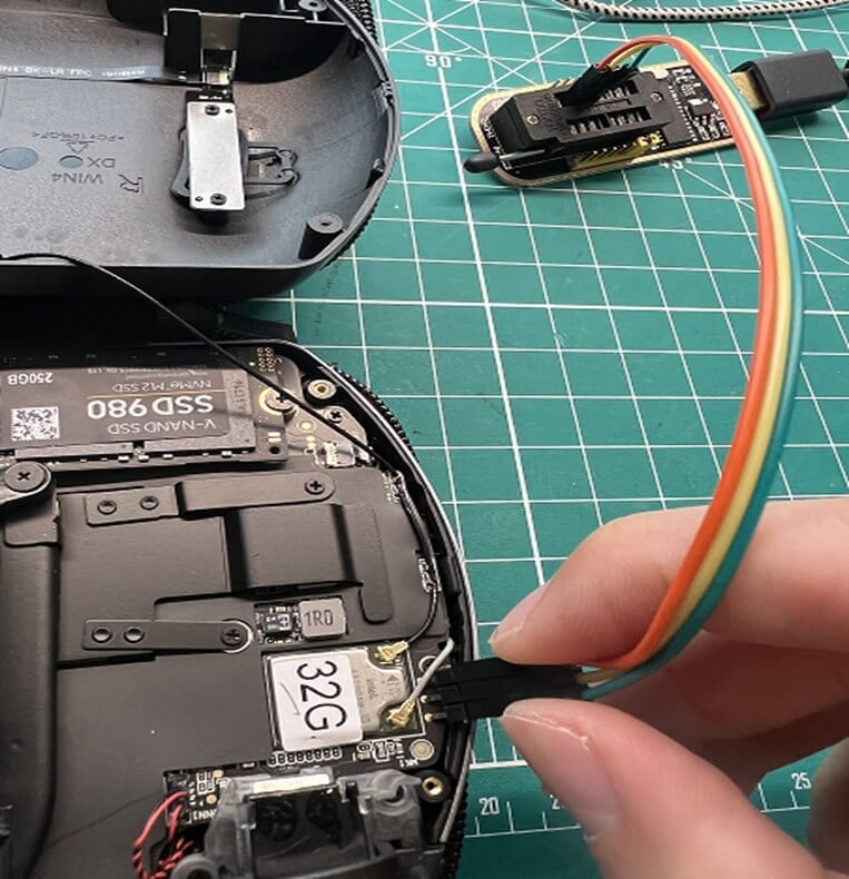
Connect the CH341a and program: Note, you will need to have your GPD Win 4 powered on and the screen turned on, to flash successfully. You may want to increase your screen timeout in Windows or boot into the BIOS during the procedure.
Press the 3 pogo pins in the correct order against the debug pads as shown above.
*** You must maintain consistent contact with all 3 debug pads with the pogo pins through the entire flashing process ***
Open the flash app again, if there is good connectivity, this time you should not get the “Get Device Addr … Failure!” error message. Check to make sure “USB – I2C ON-LINE” is blue at the bottom right.
Click the down arrow next to Prog and select load file. Find the file win4-LCD_1080x1920_20230426v1.hex. You should now see data in the Data Display box.
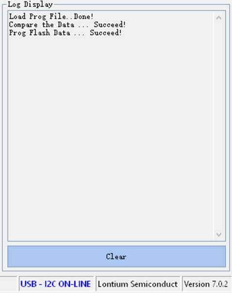
Hit the Prog button. Programming should only take about 5 seconds, there are two progress bars but they go quickly. Once complete, you should see the following in the Log Display. If the process fails, make sure the screen is still powered on, check for any error messages, and then hit Prog again. You can do this as many times as necessary – only the final successful attempt matters.
Example flashing setup (thanks tson!)
You’re all done!!! Reboot and now 60Hz should be smooth.
Unfortunately, there doesn’t seem to be a way to confirm the IC firmware version directly. An easy way to check is to use one of the many tests at www.testufo.com to confirm proper 60Hz operation. After the IC fix, you should see the same stock 60Hz and 45Hz refresh options in the Windows Display options.
If things have gone wrong, DON’T PANIC, just read further down this guide to the EMERGENCY RECOVERY INSTRUCTIONS section and follow that.
Adding 40Hz and additional CRU information:
Custom Resolution Utility (CRU)
If you had any previous CRU entries, reset them by running reset-all.exe in the CRU folder. This should result in the default 60Hz and 45Hz options being available in Windows display settings
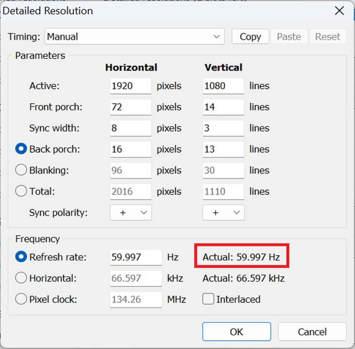
You can check if the firmware update was successful using CRU. After running reset-all.exe above, open CRU and hit edit on the first entry for 60Hz. You should see the below confirming refresh has been fixed:
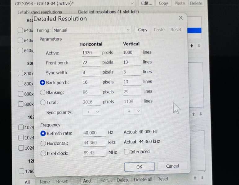
Additionally, you can add 40Hz (or any other refresh rate) using the settings below. (Thanks G Cat!) 60Hz, 45Hz, and 40Hz should all function stutter free after the firmware IC flash.
EMERGENCY RECOVERY INSTRUCTIONS
So you got a partial flash and then rebooted anyway, and now the screen won’t turn on?
First, DON’T PANIC. You cannot permanently brick the screen unless you physically damage something, for instance soldering to the pads and ripping one off. So don’t do that.
The programmer hardware is everything you need to recover from a corrupted firmware, or even a completely blank chip.
Above all else, DO NOT SOLDER TO THE PADS.
Boot the GPD WIN 4 and enter the bios by hitting DEL. If you have an external monitor then you can confirm this, otherwise you will have to do it blind. This will ensure the GPD Win 4 is powering the panel bridge IC even though the screen will still appear completely blank.
Repeat the flashing instructions from the previous section. If it fails, do it again. You can hammer the program button as many times as needed, as you only need it to succeed once.
If you still have problems then check all your wires and reposition the pins on the header to try and get a better connection. It will work when you get it right.
[azp_custom_product id=”34″]
Bringer of videos, text and images! AKA the social media guy at DROIX. Massive retro gaming fan and collector, with a far too large collection of consoles and computers from 1970's to modern. Contact me at [email protected]
Questions & comments
2Every question gets an answer. Ask before you buy — DaveC and the team reply within one working day, and answers stay public so they help the next reader too.
Way cool!!! Thank you so much for your contribution to the GPD WIN 4 community! Would it be OK if I shared this on the GPD reddit and Discord? I would give you credit and proper reference of course!
We're glad to help—and of course you can :)